The coolest vending machine

My 13 year old daughter has been fascinated by vending machines for a long time. Let’s face it, there’s something magical about making a robotic machine come to life and having it do your bidding.

For a long time we talked about making one and finally, once summer came around, I agreed to build her one.

So, what does it do?

The Coolest Vending Machine is a product dispenser with five independent compartments. It is really cool because it is refrigerated (pun intended). It is also cloud connected and even has a camera, for you to view remotely the product delivery. It is analytics ready and a full citizen of the IoT world we live in.

Electronics

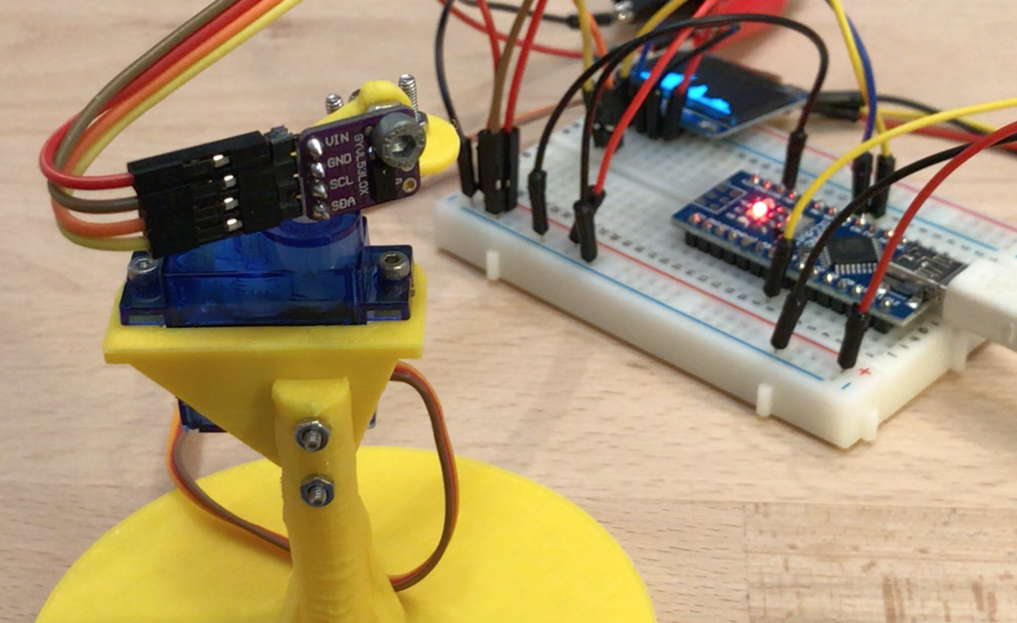
There are three MCUs in this project, connected by an I2C bus: an ESP32-CAM for cloud connectivity, an Arduino Uno to manage the systems in the front of the machine and an Arduino Nano for the back systems.

Relays are used to power components that require more power than what the Arduinos can provide, such as the Peltier element, the laser and the controller compartment fan.

As I learned in my earlier projects, it is important to have removable connectors between any two components on the system, to facilitate troubleshooting and replacement if needed.

Arduino Uno controls front systems

Most wiring was done using 20 AWG silicone insulated wire and multiple types of connectors were used, including crimp terminals and JST. The wires soldered to the Arduinos were 24 AWG, due to the size of the holes on the MCUs.

In all The Coolest Vending Machine has 226 component connections, which means twice as many wires and four times that number of soldered connections and crimped connectors.

Payment system

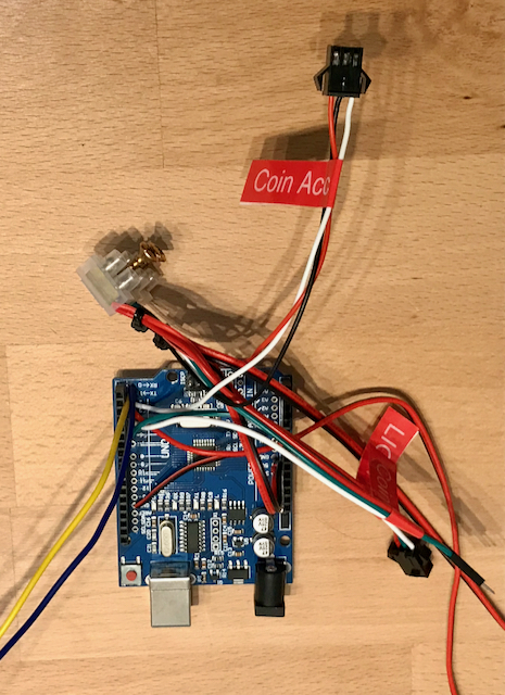
A coin acceptor was used to accept payment and a 3D printed drawer with a SG90 servo was used for refunds.

The Coolest Vending Machines allows you to pay for a product with a combination of 5 different coin values (2€, 1€, 50c, 20c and 10c). You can cancel the purchase before you complete payment and the machine will return the coins you had inserted. If it is unable to deliver the product you chose, it will refund you, but it does not provide change.

Coin acceptor and refund system

You have good tutorials on how to program the acceptor here and here. It helps if you have an oscilloscope, but it is not required. Basically the acceptor is trained to recognize a coin type and programmed to send a number of pulses when it receives such coins. In this case I programmed it to send one pulse for each 10 cents, which means it sends two pulses when a 20 cent coin is inserted, as depicted in the image below.

Coin acceptor pulses sent to Arduino when 20c coin is inserted

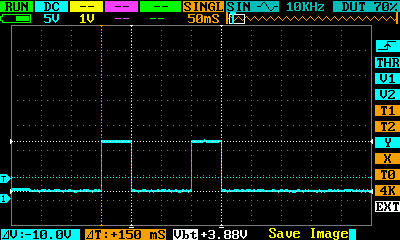
The downside of this system is that the coin acceptor will need to send the Arduino controller twenty pulses for each two Euro coin inserted, which takes 2 seconds. This is something you see in commercial machine with this type of coin acceptors – they take longer to confirm the insertion of a large value coin than a smaller value one.

Power

In the architecture diagram above different colour lines represent different voltages, so The Coolest Vending Machines uses two DC power sources to supply 5 and 10 Volt. Part of the circuit uses 3.3 V, which is provided by the ESP32-CAM.
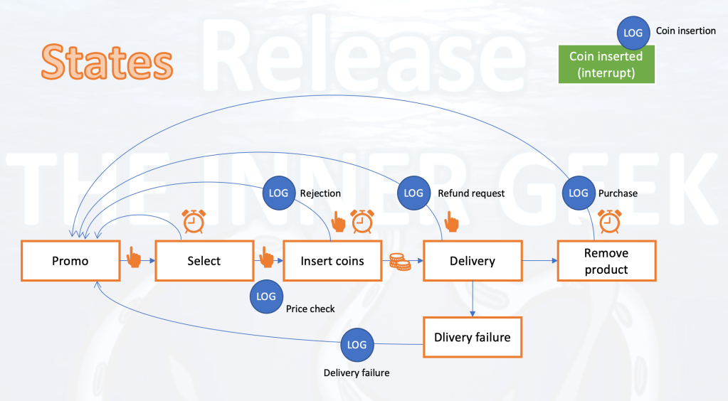
Two power sources

State diagram

The diagram below represent the sequential states when using the machine, including failure to deliver a product purchased. The LOG circles indicate what is logged to the cloud for analytics.

HMI Screens

In this project I used a Nextion HMI display (NX4832T035_011R). It’s a very cool technology because you load the screens and animations (e.g. progress bar) on the display itself and it just receives commands from the Arduino controller and sends it the inputs received on the display (e.g. button presses).

A total of 18 screens were designed, to cover the full interaction portfolio.
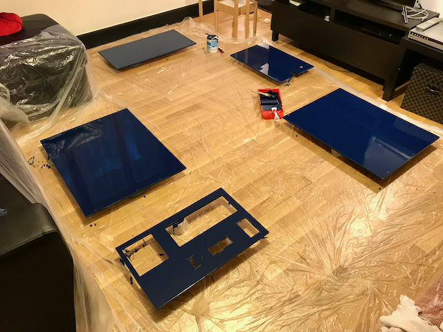
HMI screens and properties

The structure

The Coolest Vending Machine is made with plywood, painted with blue acrylic paint on the outside, and white on the inside of the product compartment.

Painted exterior panels
Coolest Vending Machine interior

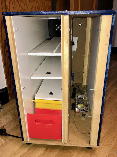
Product extraction is done with a 3D printed drawer, that lifts a ramp to prevent intrusion. The drawer closes upon release, by means of a spring.

A spring shuts the product drawer upon release.
Video of the drawer in operation

The ramp has dual color for increased depth perception.

No. Not really. I just ran out of red filament mid-print and had to switch to another color 😉

Cooling

The compartments that holds the products is refrigerated using a Peltier element placed in a hole in the back of the machine. The cold generating side of the Peltier element is directed to the inside of the machine and is attached to a metal dissipator. The hot side is attached to a fan heatsink on the outside, bonded with some heatsink plaster.

Peltier element with dissipators
Cooling system viewed from the outside

The cooling system also includes a LM35 temperature sensor (nice tutorial here), which measures the internal temperature of the machine, close to its roof.

LM35 temperature sensor

Door systems

The door of The Coolest Vending Machine has an acrylic window, lit around its border by WS2812b (neopixel) segments. Don’t forget to add a capacitor when powering these sensitive things.

The coin return system, the coin acceptor, the buzzer and the HMI display are also mounted on the door.

Systems mounted inside the door
Door from the outside

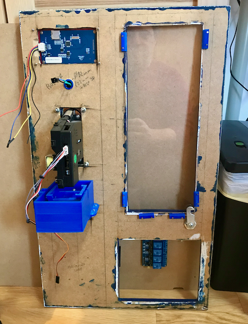
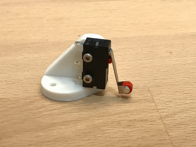
There is a contact switch on the bottom of the machine to check that the drawer is closed before starting to deliver of a product. The switch is oriented properly using a 3D printed support.

Contact switch

Product delivery

To deliver a product, a stepper turns a metal coil. When the product reaches the end of the tray it falls and intersects a red laser beam, pointed at a PGM5539 photoresistor.

Laser pointed at variable resistor

The steppers are driven by A4988 drivers with heatsinks. You have a nice tutorial here.

The steppers are held by 3D printed supports, designed in two models: one with two steppers side-by-side, for smaller products, and another with a single stepper, for larger products.

3D printed stepper supports – dual product model

Lessons learnt

The approach for this project was all wrong. After toiling away almost a year, I gave up, before a single product was dispensed. The project is a feature rich monolith and was a classic waterfall disaster.

The takeaway is that a project like this should be lean and agile, starting with a minimum viable product that you complete quickly and learn from, before iterating in order to increase functionality.

Lesson learned 🙂

If you enjoyed this project, please leave a comment. I would really enjoy hearing from you!

Teeny weeny traffic lights

Hi there!

I’m Carolina and this is my first electronics project for the Inner Geek.

On a weekend at home I had an idea, I wanted to make a model traffic light for cars and pedestrians like the ones you see on the street. I wanted to do this project to learn a little bit more about electronics and to have fun.

So, How does it work?

There are two sets of lights in this project: One for cars and one for pedestrians. There is also a button to let pedestrians cross the street.

Electronic diagrams, flowchart and prototype.

The story behind my Project.

My technology teacher asked us to make a traffic light project at school in groups, but I wanted to try to do it by myself at home because there I have more tools, materials, and time. I had learned about the Arduino before, but there were other things that I didn’t know like how to solder and isolate wires so they don’t short.

Luckily, during the project, there were no disasters, like shorts or burns, but there was a mistake. At first, when I tried to run the circuit, everything seemed to be going well: the LEDs were turning on and off correctly, except for the red LED in the pedestrian traffic light. It didn’t take me long to figure out the mistake. It turns out I had inverted the LED: the Cathode was connected to positive and the Anode was connected to ground. Such an easy mistake to make. I de-soldered the LED and re-soldered it the right way round. After that, the traffic light worked perfectly.

Traffic lights making of video

What you need to make this project:

  • Arduino Pro micro board
  • 2 green LEDs
  • 2 red LEDs
  • 1 yellow LED
  • 1 button
  • a 9v battery
  • a battery holder
  • 4 220Ω resistor

The Code

// (c) Carolina Carvalho 2021

#define GREEN_CARS 2
#define RED_CARS 4
#define YELLOW_CARS 3
#define GREEN_PEDESTRIAN 5
#define RED_PEDESTRIAN 6
#define BUTTON 7
#define BUTTON_LED 8

void setup()  {
  pinMode(GREEN_CARS, OUTPUT);
  pinMode(RED_CARS, OUTPUT);
  pinMode(YELLOW_CARS, OUTPUT);
  pinMode(GREEN_PEDESTRIAN, OUTPUT);
  pinMode(RED_PEDESTRIAN, OUTPUT);
  pinMode(BUTTON, INPUT);
  pinMode(BUTTON_LED, OUTPUT);

}

// Turn off all LEDs
void turn_off() {
  digitalWrite(RED_CARS, LOW);
  digitalWrite(YELLOW_CARS, LOW);
  digitalWrite(GREEN_CARS, LOW);
  digitalWrite(GREEN_PEDESTRIAN, LOW);
  digitalWrite(RED_PEDESTRIAN, LOW); 
  digitalWrite(BUTTON_LED, LOW);
}

void loop(){
  turn_off();
  digitalWrite(GREEN_CARS, HIGH);
  digitalWrite(RED_PEDESTRIAN, HIGH);

  // Waits for button press
  while (digitalRead(BUTTON) == HIGH) {
    // Do nothing
  }

  // Start pedestrian count down
  digitalWrite(BUTTON_LED, HIGH);
  delay(500);
   digitalWrite(BUTTON_LED, LOW);
  delay(500);
   digitalWrite(BUTTON_LED, HIGH);
  delay(500);
   digitalWrite(BUTTON_LED, LOW);
  delay(500);
   digitalWrite(BUTTON_LED, HIGH);
  delay(500);
   digitalWrite(BUTTON_LED, LOW);
  delay(500);
   digitalWrite(BUTTON_LED, HIGH);
  delay(500);
   digitalWrite(BUTTON_LED, LOW);
  delay(500);
   digitalWrite(BUTTON_LED, HIGH);
  delay(500);
   digitalWrite(BUTTON_LED, LOW);
  delay(500);
  
  turn_off();
  digitalWrite(YELLOW_CARS, HIGH);
  digitalWrite(RED_PEDESTRIAN, HIGH);
  delay(3000);
  
  turn_off();
  digitalWrite(RED_CARS, HIGH);
  digitalWrite(GREEN_PEDESTRIAN, HIGH);
  delay(5000);
  
  turn_off();
  digitalWrite(RED_CARS, HIGH);
  digitalWrite(GREEN_PEDESTRIAN, HIGH);
  delay(500);
  digitalWrite(GREEN_PEDESTRIAN, LOW);
  delay(500);
  digitalWrite(GREEN_PEDESTRIAN, HIGH);
  delay(500);
  digitalWrite(GREEN_PEDESTRIAN, LOW);
  delay(500);
  digitalWrite(GREEN_PEDESTRIAN, HIGH);
  delay(500);
  digitalWrite(GREEN_PEDESTRIAN, LOW);
  delay(500);
}

In Conclusion

This traffic light was cool to make, quick, and in my opinion it was quite easy. I recommend making this project because it is not only fun, but it’s cool to show your friends and family this nice, little project.

Walbi, the walking biped

Wouldn’t it be great if we could make a biped robot with some servos? The Inner Geek thought so and this is the result…

Walbi, design, assembly and programming

That’s Walbi, the WALink BIped, a robot we created for a Machine Learning project that never got off the ground (neither did Walbi, but that’s because it has both feet solidly planted on the ground).

Walbi standing
Walbi standing

Walbi uses an Arduino Nano for “brain”, LX-16A servos for “muscles” and plastic 3D printed parts for “bones”. The LewanSoul LX-16A servos are dream servos for small(ish) robotic projects, as they are light, can move over 19 kg.cm and are connected with a single cable, running from servo-to-servo, making cabling the robot child’s play.

LewanSoul LX-16A servos and supports
LewanSoul LX-16A servos and four support types

Walbi is a 2:1 scale humanoid and its legs are 55 cm tall (21.7 in) from heel to waist and weigh 1,1 Kg (2.4 lbs). The white parts of its body were 3d-printed, but could as easily have been made out of lightweight sturdy wood.

Walbi feet
Walbi feet

Programming Walbi is very simple. You can download below the two programs needed to do motion capture and playback, and with then you can make Walbi walk, crawl, climb, jump or dance! You only have to move its legs to a desired pose, record that pose, shape Walbi it into another pose, record it and so forth, and then, when you have recorded the complete sequence, you can seat back and watch it perform skilfully the moves you taught it.

Walbi hip detail
Walbi hip detail
Walbi in walking pose
Walbi learning to walk

Maybe you can teach yours to riverdance 😀

Building the Walbi

Walbi was 3D printed in PLA plastic, using a FlashForge Creator Pro printer. You can download the STL files from Thingiverse, or use an alternate method to build the feet, leg “bones” and waist, using wood or metal. The servo supports attach to these parts, to the servos and to one another.

STL design on 123D

As shown on the diagram below, you will need metal supports of the four different types available to attach the servos to the parts printed and to each-other.

Walbi servo support use
Walbi servo support usage

Wiring

In order to control the LX-16A servos you need a LewanSoul Debug Board.

LewanSoul Debug Board

It will receive commands from a serial port on the Arduino Nano. As we used the Arduino’s hardware serial to communicate with the computer, we had used the SoftwareSerial library to create a second serial port on the Nano, in order to connect to the Debug Board.

Wiring is minimized with serial servos. There is a cable from each servo to the next (serial cable provided with the servos) and the servos at the waist plug directly into the Debug Board. Your computer connects to the USB port of the Arduino and the Arduino is connected to the Debug Board using three jumper wires (TX, RX and GND) connected to the Arduino  pins that you configure for SoftwareSerial – we used pins 10 and 1 in the code1.

The servos use a baud rate of 115200 (if you know how to change it please tell us, as this is too high). This baud rate is high for SoftwareSerial, so we had to implement error checking and retrial functionalities. In some cases persistence was required to get a correct reading.

Power

The servos can provide 19.5kg.cm at 7.4v. We used 6v and the stall current was below three amps.

Programming

You can get the Arduino code from the Github repository.

Two programs are used for motion capture and replay, a technique similar to the one used in movies. You start by shaping the robot into a pose. As the servos default to motor off, you can rotate the servos by hand. Once you have the robot in the desired pose, you use the Walbi_record program to read and display all servo angles. You then feed those angle readings into the poseAngles variable in Walbi_play, and use the program to play back the sequence of poses recorded, at a speed set using the timeToMove variable (in mili-seconds).

We hope you enjoyed the project. Feel free to share your love by leaving a comment, subscribing the blog or any other type of feedback action.
We appreciate it!

Inner Geek nuggets

Here are some tips and tricks learned while creating Walbi:

  • The supports for the LX-16A only attach to the servo in ONE position, so it is very easy to connect them incorrectly, specially to the 3d-printed parts. We had to reassemble Walbi a couple of times to correct assemly mistakes that were quite hard to spot.
  • The servos came with ID 1 by default. Assign each servo a different ID before mounting them on the robot, or it will be impossible to communicate with multiple connected serial servos with the same ID.
  • Using cable ties really improves appearence
  • The servos come with the screws required to connect the horns to the servos and the horns to the supports. The supports come with the screws required to attach them to the servos. You will need to purchase separately screws for support to support connections and support to plastic parts connection. We used DIN912 M2-6 and M2-10 screws and nuts.
  • You can improve traction by sticking silicone pads to the soles of the robot’s feet.
  • It is preferable to use metal servo horns, as the plastic ones that come with the servos will tear if (when) the legs smash into each other during tests. If the horns tear, the robot will gain slack and movement playback will lose accuracy (which otherwise is surprisingly good).
Tear in plastic servo horn

Minimalist LiDAR

LiDAR assembled.png

A long weekend is the perfect chance to release the InneR GeeK, so this time around I built a one degree of freedom LiDAR, using a breakout board of the compact GY-530 Time-of-flight ranging sensor, which is absolutely minuscule.

Let’s start with the “ingredients”:

  • Arduino Nano (or any other, really)
  • SSD1306 OLED screen
  • VL53LOX breakout board
  • Servo (micro servo such as the sg90 is perfect)
  • 3d-printed parts (you can pick-up the STL files at the Minimalist-LiDAR Thingiverse repository)

The cabling is straightforward. You connect:

  • The OLED screen and the VL53LOX board’s GND, SCL and SDA pins (I2C) to the Arduino’s I2C pins;
  • The servo signal cable (yellow) to a digital pin (used D5);
  • The GND and 5V of the servo, OLED and VL53LOX to a 5 Volt external power source;
  • The GND of the Arduino to the GND of the external power source (if you miss this step the servo won’t budge or will move erratically).

Using the VL53LOX is straightforward. You initialize it with a few lines:

#include "Adafruit_VL53L0X.h"
Adafruit_VL53L0X lox = Adafruit_VL53L0X();
VL53L0X_RangingMeasurementData_t reading;
lox.begin();

And you take a reading using:

lox.rangingTest(&reading, false);

To access the measured value, use:

measurement = reading.RangeMilliMeter;

The hard part of the project was shrinking the code down so that it would fit the Arduino Nano’s small memory. Here are some tricks I used to reduce the code size and get it to upload and run properly:

  • Started using the <Adafruit_SSD1306.h> library to draw on the OLED screen but had to replaced it with the <U8g2lib.h> to save space;
  • Used #define for constants
  • Used byte instead of int
  • Used float instead of double
  • Calculated screen position to servo angle relations offline and loaded the results into arrays
  • Exhaled before compiling (sort of 🙂 )

Captura de Tela 2018-05-16 às 00.09.00It finally worked, but if you want to replicate this I suggest you use an ES32 or some other board with more memory.

You can download the code at the Github repository for the project

Feel free to comment, suggest, tip or provide any other kind of feedback. That’s what sharing is all about!